
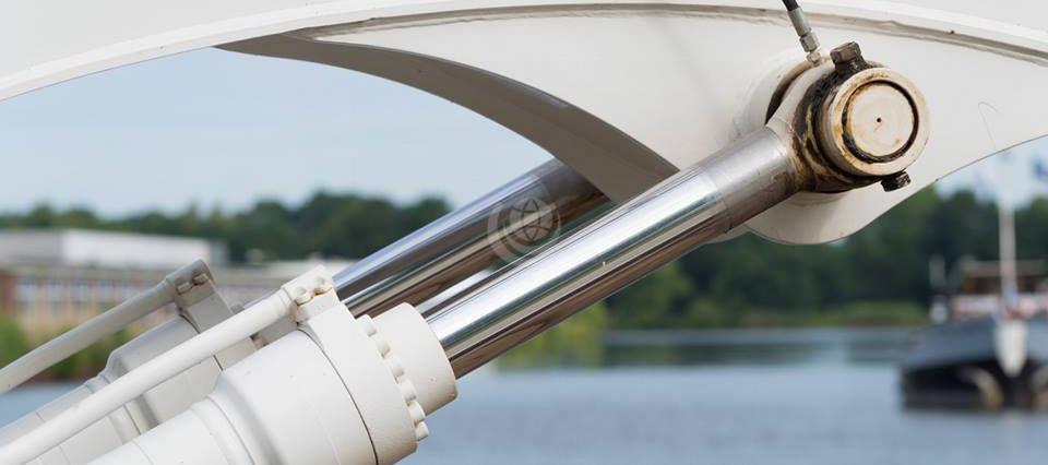
A hydraulic cylinder is the actuator or ‘motor’ side of a hydraulic system. They are sometimes referred to as the ‘muscles’, making light work of lifting, lowering, moving or ‘locking’ heavy loads.
The pump is the ‘generator’ side of the system, which brings in a fixed or regulated flow of oil to the bottom side of the cylinder. This subsequently moves the piston rod upwards. Hydraulic cylinders transform the pressure and oil flow in a hydraulic system into work or mechanical force. They are used where linear motion is required to move something.
Cylinders are also known as ‘hydraulic jacks’, ‘hydraulic rams’ or ‘actuators’. In simple terms, they convert fluid power into mechanical energy. A hydraulic cylinder differs from a hydraulic motor as it carries out a linear (translatory) rather than rotary movement. Hence the term “linear motor”.
Hydraulic cylinders produce large forces and precise movement. They are therefore constructed of strong materials, such as steel that is capable of withstanding the large forces involved.
Two construction styles
There are primarily two styles of hydraulic cylinder construction used in the industry: tie rod and welded body cylinders. Beyond this, other broad types of cylinder design include: telescopic, plunger, differential, re-phasing and single and double-acting hydraulic cylinders.
Hydraulic cylinders are usually double-acting. This means that oil under pressure can be applied to either side of the piston to provide movement in either direction. Single-acting cylinders are sometimes used where the weight of the load is used to return the cylinder to the closed position.
Hydraulic cylinders enable more flexibility in design and structure when transferring force between two different points. Different sized cylinders make it possible to create a system that can pull, push and lift weights. In addition, bends and corners can be incorporated into the system design, which is useful if there are real space constraints.
However, a hydraulic cylinder should only be used for linear pushing and pulling. No bending movements or side loads should be transmitted to the piston rod or the cylinder. For this reason, a cylinder should ideally be connected by using a single clevis with a spherical ball bearing. This enables the cylinder to move and allows for any misalignment between it and the load it is pushing.
Rephasing hydraulic cylinders
Two or more cylinders can be installed in ‘parallel’ or ‘series’. The bores and rods are then aligned, to enable all rods to extend and/or retract equally when flow is directed to the first, or last, cylinder within the hydraulic system. This is known as ‘rephasing’ hydraulic cylinders.
In ‘parallel’ applications, the bore and rod sizes are always the same, and the hydraulic cylinders are always used in pairs.
In ‘series’ applications, the bore and rod sizes are always different, and two or more hydraulic cylinders may be used. The bores and rods are sized, so that all rods extend or retract equally when flow is applied to the first or last cylinder within the system. This hydraulic synchronisation of rod positions eliminates the need for a flow divider in the hydraulic system, or any type of mechanical connection between the cylinder rods.
How cylinders work
Hydraulic cylinders, also known as ‘hydraulic rams’, get their power from pressurised hydraulic fluid, normally hydraulic oil.
The hydraulic cylinder consists of a cylinder barrel, in which a piston connected to a piston rod moves back and forth. The barrel is closed on each end by the cylinder bottom – also called the cap end – and by the cylinder head. The latter is where the piston rod comes out of the cylinder. The piston has sliding rings and seals. The piston divides the inside of the cylinder in two chambers. Firstly, the bottom chamber or cap end and secondly, the piston rod side chamber, ‘rod end’. The hydraulic pressure acts on the piston to do linear work and motion.
Flanges, trunnions, and/or clevises are mounted to the cylinder body. The piston rod also has mounting attachments to connect the hydraulic cylinder to the object or machine component that it is pushing.
A hydraulic cylinder is the actuator or ‘motor’ side of the system. The ‘generator’ side of the hydraulic system is the hydraulic pump, which brings in a fixed or regulated flow of oil to the bottom side of the hydraulic cylinder, to move the piston rod upwards. The piston pushes the hydraulic oil in the other chamber back to the reservoir. If we assume that the oil pressure in the piston rod chamber is approximately zero, the force on the piston rod equals the pressure in the hydraulic cylinder times the piston area (F=PA).
The piston moves downwards if oil is pumped into the piston rod side chamber and the hydraulic oil from the piston area flows back to the reservoir without pressure. The pressure in the piston rod area chamber is (Pull Force) / (Piston Area – Piston Rod Area).
Parts of a Hydraulic Cylinder
A hydraulic cylinder consists of the following parts:
Cylinder Barrel
The cylinder barrel is mostly a seamless thick-walled forged pipe that must be machined internally. The cylinder barrel is ground and/or honed internally.
Bottom or Cap
In most hydraulic cylinders, the barrel and the bottom are welded together. This can damage the inside of the barrel if done poorly. Therefore, some hydraulic cylinder designs have a screwed or flanged connection from the cylinder end cap to the barrel. In this type the cylinder barrel can be disassembled and repaired in future.
Cylinder Head
The cylinder head is sometimes connected to the barrel with a sort of a simple lock (for simple cylinders). In general however, the connection is screwed or flanged. Flange connections are the best, but also the most expensive. A flange is welded to the pipe before machining. The advantage is that the connection is bolted and always simple to remove.
Piston
The piston is a short, cylinder-shaped metal component that separates the two sides of the cylinder barrel internally. The piston is usually machined with grooves to fit elastomeric or metal seals. These seals are often O-rings, U-cups or cast iron rings. They prevent the pressurised hydraulic oil from passing by the piston to the chamber on the opposite side. This difference in pressure between the two sides of the piston causes the cylinder to extend and retract.
Piston seals vary in design and material to suit the pressure and temperature requirements of the hydraulic cylinder in use. Generally speaking, elastomeric seals, made from nitrile rubber or other materials, are best in lower temperature environments while seals made of viton are better for higher temperatures. Cast iron piston rings are the best seals for high temperature.
Piston Rod
The piston rod is typically a hard, chrome-plated piece of cold-rolled steel, which attaches to the piston and extends from the cylinder through the rod-end head. Double rod-end hydraulic cylinders use actuators with a rod extending from both sides of the piston and out both ends of the barrel. The piston rod connects the hydraulic actuator to the machine component doing the work. This connection can be in the form of a machine thread or a mounting attachment such as a rod-clevis or rod-eye. These mounting attachments can be threaded or welded to the piston rod or, sometimes, they are a machined part of the rod-end.
Rod Gland
The hydraulic cylinder head is fitted with seals to prevent the pressurised hydraulic oil from leaking past the interface between the rod and the head. This area is called the rod gland. It often has another seal called a rod wiper which prevents contaminants from entering the hydraulic cylinder when the extended rod retracts back into the cylinder. The rod gland also has a rod bearing. This bearing supports the weight of the piston rod and guides it as it passes back and forth through the rod gland. In some cases, especially in small hydraulic cylinders, the rod gland and the rod bearing are made from a single integral machined part.
A hydraulic cylinder should be used for pushing and pulling only. No bending moments or side loads should be transmitted to the piston rod or the cylinder. Therefore, the ideal connection of a hydraulic cylinder is a single clevis with a spherical ball bearing. This allows the hydraulic actuator to move and allow for any misalignment between the actuator and the load it is pushing.
Hydraulic Cylinder Design Types
Telescopic Hydraulic Cylinder
The length of a hydraulic cylinder is the total of the stroke, the thickness of the piston, the thickness of bottom and head and the length of the connections. Often this length does not fit in the machine. In that case the piston rod is also used as a piston barrel and a second piston rod is used.
These kind of hydraulic cylinders are called telescopic cylinders. If we call a normal rod cylinder single stage, then telescopic cylinders are multi-stage units of 2, 3, 4, 5 and even 6 stages. In general telescopic hydraulic cylinders are much more expensive than normal cylinders. Most telescopic cylinders are single-acting (push). Double-acting telescopic cylinders are made bespoke.
Tie Rod Style Hydraulic Cylinder
Tie rod style hydraulic cylinders use high strength threaded steel rods to hold the two end caps to the cylinder barrel. This method of construction is most often seen in industrial factory applications. Small bore cylinders usually have 4 tie rods, while large bore cylinders may require as many as 16 or 20 tie rods in order to retain the end caps under the tremendous forces produced.
The National Fluid Power Association (NFPA) has standardised the dimensions of hydraulic tie rod cylinders. This enables cylinders from different manufacturers to interchange within the same mountings. Tie rod style cylinders can be completely disassembled for service and repair.
We can provide you with standard and custom-made hydraulic cylinders, including tie rod hydraulic cylinders, to suit your specific application, requirements and operating parameters. Simply complete our Bespoke Cylinder Design Form and one of our hydraulic engineers will get back to you promptly.
In addition, special features are easily added to the cylinder body. These may include special ports, custom mounts, valve manifolds, and so on. The smooth outer body of welded cylinders also enables the design of multi-stage telescopic cylinders.

Welded Body Hydraulic Cylinder
These hydraulic cylinders have no tie rods. The barrel is welded directly to the end caps. The ports are welded to the barrel and the front rod gland is then usually threaded into or bolted to the cylinder barrel. This allows the piston rod assembly and the rod seals to be removed for service.
Welded body cylinders have a number of advantages over tie rod style cylinders. For instance, welded cylinders have a narrower body and often a shorter overall length, enabling them to fit better into the tight confines of machinery. Welded cylinders do not suffer from failure due to tie rod stretch at high pressures and long strokes. The welded design also lends itself to customisation.
In addition, special features are easily added to the cylinder body. These may include special ports, custom mounts, valve manifolds, and so on. The smooth outer body of welded cylinders also enables the design of multi-stage telescopic cylinders.
Moreover, welded body hydraulic cylinders dominate the mobile hydraulic equipment market. For example, in applications such as construction equipment (including excavators, bulldozers) and material handling equipment (fork lift trucks and tail lift gates). They are also used in heavy industry such as cranes, oil rigs, and large off road vehicles in above ground mining.

Piston Rod Construction
The piston rod of a hydraulic cylinder operates both inside and outside the barrel, and consequently both in and out of the hydraulic fluid and surrounding atmosphere.
Metallic Coatings
Smooth and hard surfaces are desirable on the outer diameter of the piston rod and slide rings for proper sealing. Corrosion resistance is also advantageous. A chromium layer may often be applied on the outer surfaces of these parts. However, chromium layers may be porous – attracting moisture and eventually causing oxidation.
In harsh marine environments, the steel is often treated with both a nickel layer and a chromium layer. Often 40 to 150 micrometre thick layers are applied. Sometimes solid stainless steel rods are used. High quality stainless steel such as AISI 316 may be used for low stress applications. Other stainless steels such as AISI 431 may also be used where there are higher stresses, but lower corrosion concerns.
Ceramic Coatings
Ceramic coatings were developed, due to shortcomings of metallic materials. Initially ceramic protection schemes seemed ideal, but porosity was higher than projected. Recently the corrosion resistant semi-ceramic Lunac 2+ coatings were introduced. These hard coatings are non-porous and do not suffer from high brittleness.
Lengths
Piston rods are generally available in lengths, which are cut to suit the application. As the common rods have a soft or mild steel core, their ends can be welded or machined for a screw thread.