Selecting a Hydraulic Flow Divider
Learn how to size and configure flow dividers for equal, unequal, and pressure-intensifying applications.
A geared hydraulic flow divider contains internal rotating components, making operational speed critical to achieving consistent and reliable performance…
The ideal rotation speed depends on two key variables: the oil flow rate per element and the displacement capacity per revolution of the specific flow divider design.
While most hydraulic flow dividers operate efficiently between 750 rpm and 3000 rpm, optimal performance is typically achieved within the 1000 rpm to 2000 rpm range. Staying within this window ensures minimal wear, better flow control, and improved system balance.
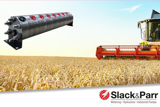
Each divider element is responsible for splitting the oil flow, and selecting the right combination allows engineers to tailor total flow output to system requirements. This guide – produced in collaboration with Slack & Parr – outlines available flow divider options based on capacity ranges:
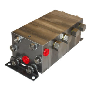
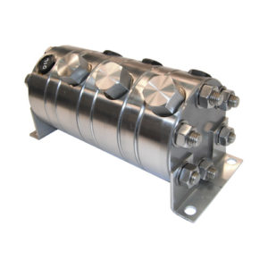
- Slack & Parr FDR Range: 2, 4, 6, and 9 cc/rev capacities
- Slack & Parr FDL Range: 12, 18, 24, and 30 cc/rev capacities
Choosing the appropriate hydraulic flow divider depends on both the application’s flow demands and its operating speed range. Balancing these factors helps ensure system efficiency, fluid synchronisation, and long-term durability.
Hydraulic Flow Divider Applications and Sizing Considerations
Although constructed from standardised components, Slack & Parr hydraulic flow dividers offer versatile functionality across multiple use cases. They can be configured in the following ways:
- Equal Flow Divider: Splits a single supply into evenly distributed streams – typically between 2 to 6 divisions, though custom configurations allow for more.
- Unequal Flow Divider: Divides fluid into streams of differing volumes based on application requirements.
- Pressure Intensifier: Boosts pressure in a portion of the flow path, ideal for systems requiring localised high-pressure operation.
Each application demands a tailored sizing approach. In new system designs, the supply flow can be calculated and defined after the flow divider is selected. However, when retrofitting a hydraulic flow divider into an existing system, it’s essential to account for the pre-established supply characteristics to ensure compatibility and performance accuracy.
 »
»
 »
»
 »
»
Selecting a Hydraulic Flow Divider for Equal Flow Applications
Where the supply rate is known
Follow these steps to calculate the correct configuration:
- Divide the supply flow by the total number of divisions required (typically 2 to 6).
- Convert the flow rate into cubic centimetres per minute (cc/min) for compatibility with divider specifications.
- Divide the cc/min value by the optimal operating speed – generally 1500 rpm – to determine the target displacement per revolution.
- Select the nearest available element size that matches the calculated displacement.
- Confirm the actual operating speed of the selected flow divider element to ensure it remains within the recommended range (1000–2000 rpm for geared designs).
This method ensures accurate flow division and helps optimise pressure balance and synchronisation across all outlets.
Selecting a Hydraulic Flow Divider for a 50:50 Split
To illustrate how to size a 2-way hydraulic flow divider, let’s walk through a practical example using known supply flow and optimised speed parameters.
Scenario:
Supply flow rate: 1000 litres/hour. Desired split: 50:50 across two outlets
Step-by-Step Calculation:
- Divide the supply flow: 1000 litres/hour ÷ 2 = 500 litres/hour per outlet
- Convert flow to cc/min: 500 litres/hour × 1000 ÷ 60 = 8333 cc/min
- Calculate ideal displacement per revolution: 8333 cc/min ÷ 1500 rpm (target speed) = 5.55 cc/rev
- Select the nearest available divider element: Use 6 cc/rev from Slack & Parr’s FDR range
- Verify actual operating speed: 8333 cc/min ÷ 6 cc/rev = 1388 rpm, which sits comfortably within the optimal performance range of 1000–2000 rpm.
Outcome:
A Slack & Parr 6 cc/rev hydraulic flow divider element operating at 1388 rpm delivers accurate 50:50 flow division within ideal parameters for speed and displacement.
Sizing a Hydraulic Flow Divider when Individual Flow Rate is Known
If the required individual delivery flow rate is known for each outlet, selecting the correct hydraulic flow divider element becomes a straightforward process. Follow these steps:
- Convert flow rate to cubic centimetres per minute (cc/min) to align with divider specifications.
- Divide cc/min by 1500 rpm, the typical mid-range operating speed, to determine the ideal displacement per revolution.
- Select the closest available divider element size – based on manufacturer offerings like Slack & Parr’s FDR and FDL ranges.
- Verify the actual operating speed by dividing the target flow rate (cc/min) by the chosen element’s displacement (cc/rev). This ensures the selected setup falls within the recommended rpm range (1000–2000 rpm).
This approach helps ensure balanced performance, accurate division, and fluid synchronisation across all outputs – especially in precision-driven applications.
Selecting a Hydraulic Flow Divider for Unequal Flow Applications
When selecting a hydraulic flow divider for unequal flow distribution, the core principles remain consistent with equal-flow setups – but require additional consideration for output ratios and element compatibility.
Follow these steps to ensure correct sizing and configuration:
- Choose an element size for each desired flow rate that aligns with an operating speed near 1500 rpm, the optimal performance midpoint.
- Keep in mind: All divider elements rotate at the same speed, so each must be compatible. FDR and FDL elements cannot be mixed within a single unit.
- Determine element combinations that achieve your desired ratio. For example, a setup with three equal-sized elements – two supplying one stream, and one supplying another – can deliver a 2:1 flow split.
- Confirm operating speed for each selected element by dividing the target flow rate (cc/min) by its displacement (cc/rev). Ensure the result falls within the ideal range of 1000–2000 rpm (or acceptable working range if needed).
This approach balances speed, volume, and mechanical integrity, delivering precision in applications where flow rates must vary across multiple outputs.
Alternatively, contact our technical team; they will be able to help you select the right configuration for your required flow ratio.
Using a Hydraulic Flow Divider for a 60:40 Split
Here’s a working example of how to size a 2-way hydraulic flow divider to achieve a 60:40 oil flow split:
Scenario:
Total supply flow: 1000 litres/hour Required split:
- Side A: 600 litres/hour
- Side B: 400 litres/hour
Step-by-Step Calculation:
- Convert flow rates to cc/min:
- 600 litres/hour × 1000 ÷ 60 = 10,000 cc/min
- 400 litres/hour × 1000 ÷ 60 = 6,666 cc/min
- Calculate target displacement per revolution (at optimal speed of 1500 rpm):
- 10,000 ÷ 1500 = 6.66 cc/rev
- 6,666 ÷ 1500 = 4.44 cc/rev
- Select nearest available flow divider elements:
- Use 6 cc/rev and 4 cc/rev elements from Slack & Parr’s range
- Verify operating speed (same for both elements):
- 10,000 cc/min ÷ 6 cc/rev = 1666 rpm
- Automatically applies to the 4 cc/rev element too (Within the optimal operating range of 1000–2000 rpm)
Selecting a Hydraulic Flow Divider for Pressure Intensification
In systems where all but one outlet flow is piped directly to tank – meaning there’s minimal outlet pressure – the energy from the supply pressure can be strategically redirected to intensify the pressure in the remaining output. This setup allows a hydraulic flow divider to act as a pressure multiplier for specific tasks.
Basic Pressure Intensification Equation (Two Elements)
To calculate the intensified pressure P1 at the high-pressure outlet:
- P1: Pressure at high-pressure element
- P2: Pressure at low-pressure (typically tank) outlet
- Ps: Supply (inlet) pressure
- E1: Displacement capacity of high-pressure element
- E2: Displacement capacity of low-pressure element
Accounting for Rotational Load Pressure
To factor in the pressure needed to rotate the flow divider (PR, assumed at 17 Bar):
This more precise equation helps engineers ensure reliable output pressure without overloading the system or misjudging operating margins. Selecting flow divider elements with the appropriate displacement values E1 and E2 is key to maximising pressure gain.
Example: Using a Hydraulic Flow Divider for Pressure Intensification
Let’s illustrate how a hydraulic flow divider can intensify pressure using equal element sizing and strategic flow design.
Scenario
- Flow Divider: Two equal elements, each with 9 cc/rev capacity
- Supply Pressure (Ps): 100 bar
- Outlet Pressure at Low-Pressure Element (P2): 0 bar (returned to tank)
- Rotational Load Pressure (PR): 17 bar
Calculation
Using the pressure intensification formula:
Substituting values:
This result shows a significant pressure boost in the high-pressure outlet – achieved simply by redirecting flow and using equal-sized divider elements.
Alternative Configurations
Greater or more targeted intensification can be achieved by:
- Reducing flow rate while keeping pressure constant
- Adjusting element capacity ratios, such as using different displacement sizes (E1 ≠ E2)
- Using unequal flow divider configurations to direct more energy to high-pressure paths
This approach allows engineers to fine-tune system pressure output without resorting to additional pumps or external amplification components.
We are the first choice for customers in over 130 countries worldwide, supplying a vast selection of hydraulic brands and components. You are guaranteed impartial, technical advice and optimal solutions. Every time.
Expand your hydraulic knowledge with more content from our Fluid Power Technical Knowledge Hub…

Hydraulic Calculations
Precision matters in hydraulic system design – accurate calculations are key to performance and efficiency.
To support your project, we’ve compiled a quick-reference guide with essential formulas and key parameters, helping you streamline design, troubleshooting, and optimisation.
Stay ahead with expert Hydraulic Insights
Subscribe now for free technical guides, product updates, industry news and trends.
*required