The hydraulic reservoir plays an important part in hydraulic circuit design – storing hydraulic fluid when it isn’t being pushed through the hydraulic system.
Before we begin looking at hydraulic reservoirs in more detail, it is worth reminding ourselves how hydraulic systems work and the role that a hydraulic reservoir plays within the overall system.
Hydraulic systems are designed to transmit power, in a controlled way, through the use of pressurised liquids. There is a finite amount of hydraulic fluid in the system that is stored and reused continually as the system operates. This makes a fluid storage tank – or reservoir – an essential part of any hydraulic system.
The hydraulic reservoir actually fulfils a number of functions within the hydraulic system as it:
- Holds a volume of fluid
- Transfers heat from the system
- Allows solid contaminants to settle, and
- Facilitates the release of air and moisture from the fluid.
While a “fluid storage tank” might seem like a very simple concept, the design and implementation of the reservoir is very important. The efficiency of even the most well-designed hydraulic system can be undermined by poor hydraulic reservoir design.
What are the design considerations when specifying a hydraulic reservoir?
#1. Size matters
The general rule when specifying a hydraulic reservoir depends on whether the system is open- or closed-circuit. For most industrial applications the tank volume should be between 3 and 5 times the pump flow/minute, with 2.5 times flow as a minimum. While this holds true in most situations, there are occasions where it may be desirable for tanks to be larger than this – for example, to ensure the fluid level remains above the pump inlet line, or when fire resistant fluids are being used.
Conversely, there may be reasons for a smaller tank to be preferable – for example, if the overall design should be lightweight or compact.
It is worth noting that smaller reservoirs may have less surface area for heat transfer, so a heat exchanger or cooler may need to be added to the design to ensure that the fluid temperature remains within acceptable parameters.
Furthermore, smaller reservoirs can be more prone to foaming and agitation of fluid when the hydraulic fluid is returned to the tank. A flow diffuser will help to minimise these issues by reducing the velocity of return fluid. This is important because aerated fluid can cause pump damage, cavitation or premature failure.
#2. Contaminants and filtration
More than half of hydraulic components will fail if the contamination levels of the fluid in the hydraulic system are too high.
You can learn more about the sources and effects of fluid contaminants in a hydraulic system via the fantastic online content at LunchBox Sessions. Served up in the form of bite-sized training sessions, most of their interactive learning materials are reserved for subscribers. But each session includes some free taster materials available to all – and that’s where the images in this article have been sourced from. LunchBox Sessions have kindly allowed us to reproduce some of their e-learning content here.
We encourage you to take a look: it’s a fantastic online resource if you want to know more about how hydraulics and other industrial technologies work.
 »
»
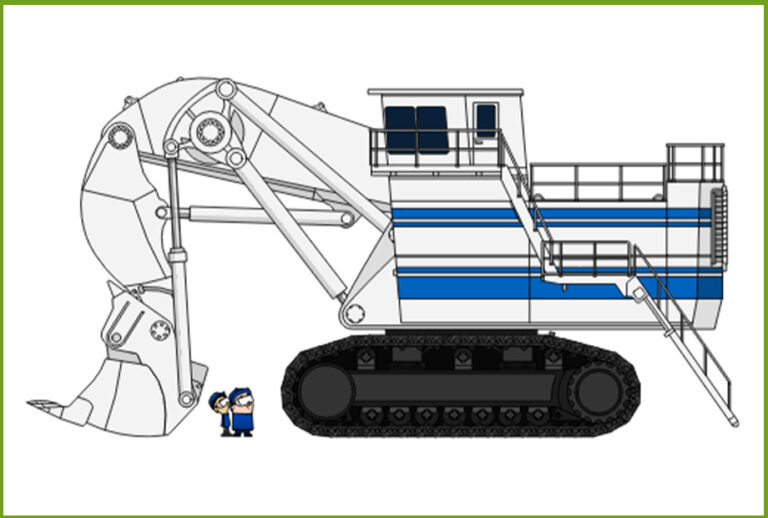
“Older hydraulic systems featured lower operating pressures, simple gear pumps and lever operated directional valves. Particle contaminants may have caused some degradation, but this seldom caused intermittent or catastrophic failure.”
 »
»
“Modern hydraulic systems feature valves with close tolerances between parts, and variable current solenoids that use minimal force. This means that particle contaminants can easily interfere with normal operations.” (LunchBox Sessions)
Now, even in a closed system, fluid contamination can come from a variety of internal or external sources, but one common source is via the breather in the hydraulic reservoir.
Hydraulic tanks require breathers to allow air in and out of the tank:
- Air is drawn into the hydraulic reservoir through the breather when the pump retracts, and the fluid is drawn into the hydraulic cylinder;
- Air is released by the breather as fluid is displaced by the pump and returned to the reservoir.
The role of the breather is discussed in more detail in this LunchBox Sessions video.
If the passage of air out of the reservoir is restricted or blocked, the internal pressure can rise above safe levels, potentially causing serious leaks.
If too little air is allowed into the reservoir, a partial vacuum will be created which can lead to cavitation, damage the pump, and diminish flow rates within the system.
For this reason, a mesh filter is usually included in the breather design. This must be monitored to ensure it doesn’t get clogged. A differential pressure switch can indicate when the filter is becoming clogged.
However, a mesh filter won’t prevent all problems. As well as filtering out dirt and other solid contaminants, the filter needs to ensure water doesn’t enter the reservoir. In a hydraulic system, water can degrade the hydraulic fluid and cause erratic operation or lead to component failure. Water can enter the system via the breather simply due to moisture in the air.
The solution to this is to use a desiccant filter breather, which uses fine particulate filters and a bed of desiccant to trap moisture from the air before it enters the hydraulic reservoir. A desiccant filter breather will also need to be monitored and maintained, as filter elements will eventually become clogged and the desiccant will be depleted over time.
In this way, you can ensure that any air pulled into the header space in the hydraulic reservoir will be clean and dry – thereby reducing the likelihood of contaminants entering your hydraulic system.
#3. Additional filtration
Hydraulic reservoirs were traditionally specified at a size that would allow contaminants to sink to the bottom of the reservoir in such a way that they are prevented from circulating in the hydraulic system.
However, an auxiliary inlet and outlet port can be added to the reservoir to allow for the addition of a “kidney loop”. Such a loop consists of a circulating pump, filter housing, and connecting hose or tubing. In this way, fluid can be filtered and returned to the hydraulic reservoir.
This additional filtration helps to further reduce the risks of contaminants in the hydraulic system.
#4. Monitoring and maintenance
We’ve mentioned that filters and breathers must be monitored and maintained to ensure their effective ongoing operation.
The cost of sensors and communication today, means that it is often cost effective to add other automated monitoring to your hydraulic systems. For example, since heat is a major cause of hydraulic fluid degradation, you may wish to add temperature monitors to your hydraulic reservoir.
While high temperature readings will require switches for safe, rapid shutdown, in cold environments a thermostatically-controlled fluid heater may be required. Cold, thick fluid can also cause damage to pump suction lines and pumps.
Finally, fluid level indicators are another important feature to include in the reservoir design. If you’re not measuring automatically, specifying a switch to signal when the fluid level becomes dangerously low will help to prevent catastrophic and expensive repairs.
More about hydraulic tanks and reservoirs
If you would like to learn more about hydraulic reservoirs, head to LunchBox Sessions’ training on contaminants and filtration here. Some of their learning materials are free; you don’t need to sign up. However, if you are serious about expanding your knowledge of hydraulic systems, we recommend you consider signing up for a subscription to the entire Lunchbox Sessions service. This way, you get full access to all the interactive training materials, tests and simulations for a monthly or annual fee. Students are entitled to a discount when they share their college or university ID.
If you haven’t found the answers you need in this article, you can find more free guides and resources in our Technical Knowledge Hub, and our expert team is always on hand to help.
Alternatively, as a leading global hydraulic equipment supplier, you can view our selection of hydraulic filters here. We only showcase a small selection of the hydraulic filters that we can supply, so please do not hesitate to contact our friendly team for personal service and advice or to find out more about our design consultancy services.
We’re a hydraulics ‘hub’, offering thousands of possibilities… how can we help?
Discover more of our collaborative content with Lunchbox Sessions
Using Pressure Readings to Diagnose Problems
Effective troubleshooting of problems in hydraulic systems requires a good understanding of flow and pressure readings.
In this article, we’re going to look at how pressure and flow can vary depending on the type of hydraulic system and what implications this has for hydraulic system troubleshooting.
Learn moreAn Introduction to Hydraulic Pressure and Flow
Hydraulic systems are based on the principles of fluid dynamics; this important branch of science deals with the movement of fluids.
One of the first concepts that must be understood is how physicists quantify the movement of fluids, namely flow.
Learn moreSpecifying Hydraulic Hoses
Hydraulic hoses convey the hydraulic fluid around the hydraulic system; they are not minor accessories.
No matter how big or small, a hose burst failure on a hydraulic system is always a catastrophic incident. Careful consideration must always be given to their specification and installation.
Learn more


