
Essential Hydraulic Formulas and Basic Principles: Key Calculations and Parameters for System Performance.
Hydraulic engineering relies on fluid dynamics, a fundamental branch of physics that explains how fluids move. Mastering these principles is essential for designing, maintaining, and optimising hydraulic systems and their performance.
By applying key hydraulic formulas, engineers can calculate critical system properties. Below, we’ve compiled some of the most important calculations for force, pressure, speed, flow rate, and power—all vital to hydraulic system performance.
Basic Hydraulic Principles
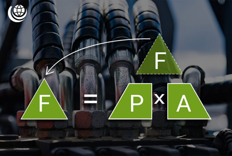
Force, Pressure and Area
The relationship between force (F), pressure (p), and area (A) can be expressed using the following formulas:
- F = p × A
- p = F / A
- A = F / p
📌 Where:
- F = Force (N)
- p = Pressure (Pa)
- A = Area (m²)

Speed, Flow Rate and Area
Hydraulic systems depend on precise calculations of flow rate (Q) and speed (S) related to a given area (A):
- Q = S × A
- S = Q / A
- A = Q / S
📌 Where:
- S = Speed (cm/s)
- Q = Flow Rate (cm³/min)
- A = Area (cm²)

Looking for clear, practical insights into hydraulic engineering? Get started with our free Beginner’s Guide to Hydraulic Engineering eBook—your essential resource for mastering the fundamentals.
Need a quick reference for hydraulic terminology? Our Hydraulics Glossary covers 140+ essential terms used in fluid power engineering – perfect for clarity and precision.
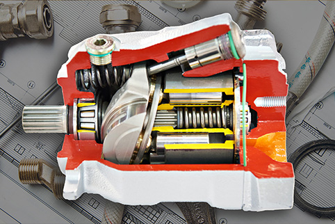
Hydraulic Formulas for Motors and Pumps
Although hydraulic motors and pumps may appear similar, they perform distinct functions. A hydraulic pump uses an external power source – such as an engine or electric motor – to generate fluid flow within a system. In contrast, a hydraulic motor converts this fluid movement into rotational force.
Below are key hydraulic formulas to calculate essential parameters for pumps and motors.
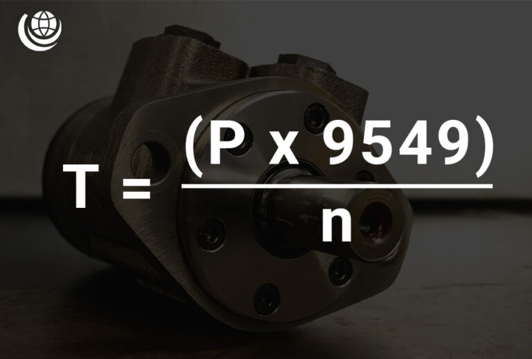
Torque Calculation (T)
Torque (T) is a crucial parameter in hydraulic systems, directly linked to power (P) and speed (n). The formula for calculating torque is:
- T = (P × 9549) / n
📌 Where:
- T = Torque (Nm)
- P = Power (kW)
- n = Speed (rpm)
- 9549 = Constant
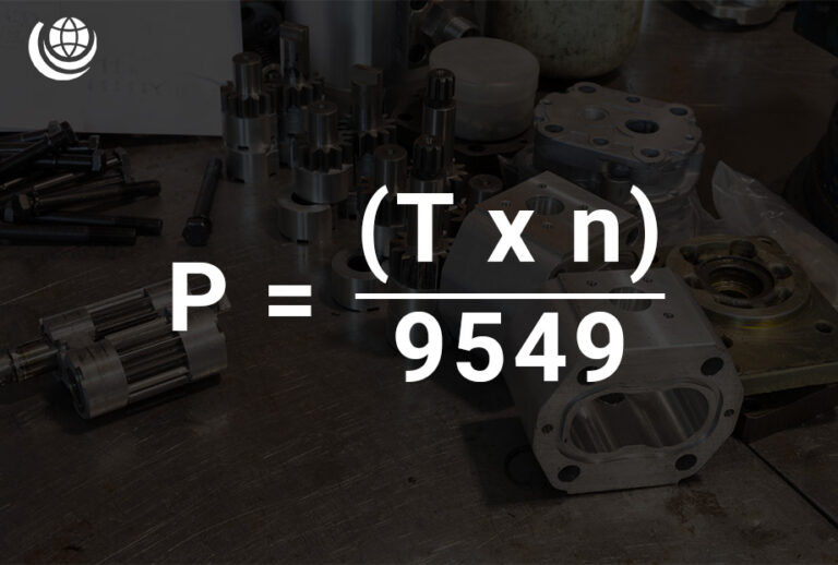
Power Calculation (kW)
Power (P) is a key factor in hydraulic systems, directly linked to torque (T) and speed (n). The formula for calculating power is:
- P = (T × n) / 9549
📌 Where:
- P = Power (kW)
- T = Torque (Nm)
- n = Speed (rpm)
- 9549 = Constant
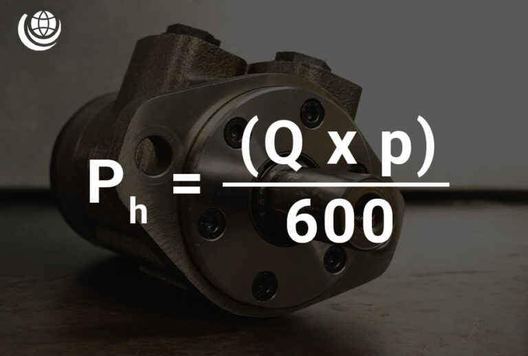
Hydraulic Power Calculation
Hydraulic power (Ph) is a fundamental measurement in hydraulic systems, determined by flow rate (Q) and pressure (p). The formula for calculating hydraulic power is:
- Ph = (Q × p) / 600
📌 Where:
- Ph = Hydraulic Power (kW)
- Q = Flow Rate (l/min)
- p = Pressure (bar)
- 600 = Conversion constant
Torque Calculation (T)
In hydraulic systems, torque (T) can be derived from displacement (D) and pressure (p) using the following formula:
- T = (D × p) / 20π
📌 Where:
- T = Torque (Nm)
- p = Pressure (bar)
- D = Displacement (cm³/rev)
- 20π = Constant
Displacement Calculation (D)
Displacement (D) in a hydraulic system can be determined using torque (T) and pressure (p) with the following formula:
- D = (T × 20π) / p
📌 Where:
- D = Displacement (cm³/rev)
- T = Torque (Nm)
- p = Pressure (bar)
- 20π = Constant

Flow Rate Calculation (Q)
Flow rate (Q) in a hydraulic system depends on pump displacement (D) and speed (n). The formula to calculate flow rate is:
- Q = (D × n) / 1000
📌 Where:
- Q = Flow Rate (l/min)
- D = Pump Displacement (cm³/rev)
- n = Speed (rpm)
- 1000 = Constant (converts cm³/min to l/min)

Expert hydraulic solutions, worldwide. Our trusted expertise and product range support industries across the globe. Download the Hydraulics Online WebApp today for instant access, no matter where you operate.
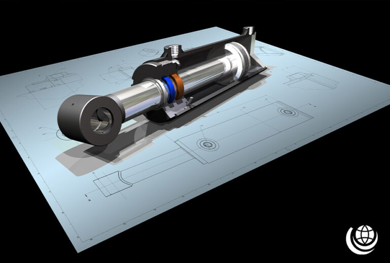
Hydraulic Formulas for Hydraulic Cylinders
Hydraulic cylinders are key components in hydraulic systems, functioning as linear actuators that generate force for lifting, lowering, or moving heavy loads. Like muscles in a machine, they rely on hydraulic fluid to perform powerful mechanical movements. Below are essential hydraulic formulas for calculating important cylinder parameters.

Piston Area Calculation (A)
The piston area (A) of a hydraulic cylinder is determined using the bore diameter (d). The formula is:
- A = πd² / 4
📌 Where:
- A = Area (cm²)
- d = Bore Diameter (cm)

Annulus Area Calculation
The annulus area (A₃) in a hydraulic cylinder is determined by subtracting the rod area (A₂) from the piston area (A₁). The formula is:
- A₃ = A₁ – A₂
📌 Where:
- A₁ = πd₁² / 4 (Piston Area)
- A₂ = πd₂² / 4 (Rod Area)
- A₃ = Annulus Area
Force, Area & Pressure Calculation
Understanding the relationship between force (F), pressure (p), and area (A) is essential in hydraulic systems. The following formulas define their interdependence:
- F = p × A
- p = F / A
- A = F / p
📌 Where:
- F = Force (N)
- p = Pressure (Pa)
- A = Area (m²)
Speed, Flow Rate & Area Calculation
In hydraulic systems, speed (S), flow rate (Q), and area (A) are closely linked. These formulas help determine fluid movement efficiency:
- Q = S × A
- S = Q / A
- A = Q / S
📌 Where:
- S = Speed (cm/s)
- Q = Flow Rate (cm³/min)
- A = Area (cm²)

Pressure Drop Calculations in Hydraulic Systems
As hydraulic fluid flows through a system, pressure naturally decreases due to pipeline resistance, bends and directional changes, and system components like valves and fittings. Different calculation methods apply depending on the cause, ensuring accurate assessment for system efficiency and performance optimisation.

Pressure Drop due to Flow Change Calculation
As fluid flows through a hydraulic system, changes in flow rate (Q) can result in a pressure drop (Δp). This relationship is defined by the following formula:
- Δp₂ = Δp₁ × (Q₂ / Q₁)²
📌 Where:
- Δp₁ = Pressure before Flow Change (bar)
- Δp₂ = Pressure after Change in Flow (bar)
- Q₁ = Original Flow Rate (l/min)
- Q₂ = Flow Rate After Change (l/min)
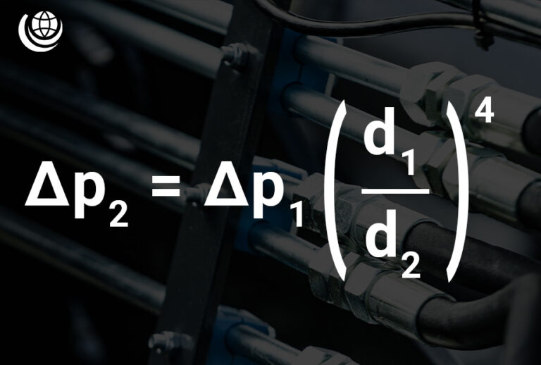
Pressure Drop at a Change of Diameter Calculation
A change in pipe diameter (d) affects fluid resistance, leading to a pressure drop (Δp). This relationship can be calculated using:
- Δp₂ = Δp₁ × (d₁ / d₂)⁴
📌 Where:
- Δp₁ = Initial Pressure (bar)
- Δp₂ = Pressure after Diameter Change (bar)
- d₁ = Original Pipe Diameter (mm)
- d₂ = New Pipe Diameter (mm)
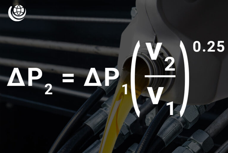
Pressure Drop due to Viscosity Change Calculation
Fluid viscosity (v) plays a crucial role in hydraulic system efficiency. A change in viscosity affects resistance, leading to a pressure drop (Δp). The relationship is defined by:
- Δp₂ = Δp₁ × (v₂ / v₁)0.25
📌 Where:
- Δp₁ = Initial Pressure (bar)
- Δp₂ = Pressure after Viscosity Change (bar)
- v₁ = Original Fluid Viscosity (cSt)
- v₂ = New Fluid Viscosity (cSt)
Stay ahead with expert Hydraulic Insights
Subscribe now for free technical guides, product updates, industry news and trends.
*required
We’re a hydraulics ‘hub’, offering thousands of possibilities
How can we help?