You may know that properly maintaining a hydraulic pump will ensure maximum efficiency and prevent damage, but did you know that it is especially critical to regularly monitor inlet conditions? Poor inlet conditions can result in cavitation – the second leading cause of pump failure.
What is pump cavitation and how can you prevent it?
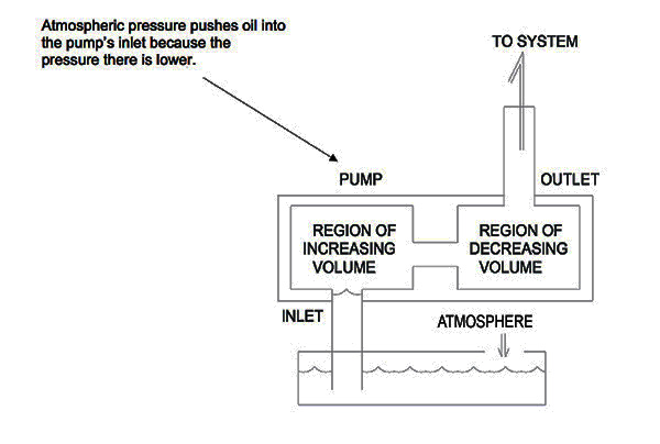
While it’s common for people to think that a hydraulic pump’s inlet sucks in the oil, in reality, it is atmospheric pressure doing the work. In essence, the weight of the atmosphere pushes the oil out of the reservoir and into a region of lower pressure – the inlet. Once the oil is forced from the reservoir and through the inlet, it then moves the volume of liquid into a region of decreasing volume to create flow. For this process to begin, there must be minimum pressure at the inlet of a hydraulic pump, as shown in the diagram below.
As you can see, the inlet of a pump plays a large role in how well it operates. Unfortunately, those designing and maintaining pump systems can become so focused on downstream flow that they overlook proper inlet maintenance. This can result in degradation of inlet function and serious problems such as cavitation.
Cavitation occurs when the absolute pressure on the inlet side of the pump is too low and air is drawn out of the solution, creating bubbles in the oil. As these bubbles get pushed around to the high-pressure outlet side of the pump, they collapse. This creates localized shock waves that blow bits of material out of the pump. It can also result in excessive heat and reduced lubrication that leads to friction and wear over time.
Cavitation can cause pump failure and it can damage other components of your system, which is why it is critical to examine the condition of the pump’s inlet on a regular basis.
Analyzing inlet conditions on steady-state and variable-flow pumps
PSI versus PSIA. What’s the difference? PSI, or pounds per square inch, is a unit of measurement for pressure commonly used in the United States. PSIA describes the absolute pressure in psi, including the pressure of the atmosphere. Absolute pressure is also referred to as total pressure.
Maintaining steady-state hydraulic pumps
There are two areas you should monitor to maintain minimum inlet pressure on steady-state pumps:
- The energy it takes to lift oil through the suction line (including pressure drop due to flow). We refer to this action as Phase 1 pressure, because it represents the amount of energy it takes to accelerate the fluid through the pumps internal pathways and keep the pump full.
- The minimum absolute pressure the pump must have in order to avoid damage. This is known as the Net Positive Suction Head, or NPSH.
In order for a pump to function, atmospheric pressure must be greater than Phase 1 pressure + NPSH. Every pump has its own specifications regarding acceptable minimum/maximum inlet pressure, but we can use the example below to illustrate how to calculate it.
To begin, assume that you are maintaining an 18 GPM hydraulic pump. The NPSH is equal to 12 PSIA with standard hydraulic oil and 1800 RPM per manufacturer’s specifications.
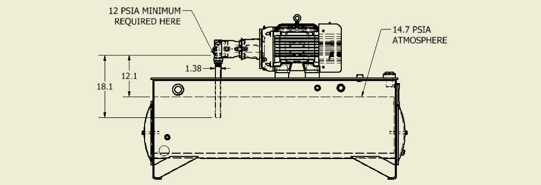
As you can see in the diagram above, the inlet line is 1.38” in diameter x 18.1” long with a 12.1” lift using standard petroleum-based fluid.
Each foot of oil lift requires approx. = 0.4 PSI. Fluid velocity is 3.8 feet per second. A typical lookup table shows there will be a 0.05 PSI drop due to the flow through the pipe.
Total loss of the inlet line during steady state is 0.4 PSI + 0.05 PSI, or 0.45 PSI. 14.7 – 0.45 = 14.25 PSI. Because this final number – 14.25 PSI – is greater than the NPSH of 12 PSIA, you can rest assured the system is functioning well.
Maintaining variable-flow hydraulic pumps
If we apply the same numbers to a variable-volume pump, the result will be less acceptable. Here’s why:
Imagine the pump is not in demand and is therefore being held off stroke, meaning there is no flow. When the pump is suddenly needed, it will come on stroke, requiring the column of oil in the suction line to accelerate. This sudden change in demand requires the pump pressure to accelerate from static to a pressure that is strong enough to move the oil and prevent cavitation.
Let’s look back at our model, applying revised numbers.
Assume the pump strokes on in 70 milliseconds (msec). The volume of liquid that has to accelerate is 1.5in^2 x 18.1” = 27.1 cubic inch (cu. in.). Note: Since the entire column of oil in the pipe has to accelerate, we used a measurement of 18.1” instead of 12.1”.
To calculate the weight of oil in the inlet line, we multiply the volume (27.1 cu. in.) by specific weight (0.0314 lbs./cu. in.), equaling 0.85 lbs. Fg (gravity force) = 0.85 lbs.
Fa = mass x acceleration
a = v/t = 3.8/0.07 = 54.3ft/sec^2
Fa = (0.85/32.2) x 54.3 = 1.4 lbs.
Ft = 0.85lbs + 1.4 lbs. = 2.25 lbs.
The available force in the pipe from the atmosphere (Fluid power (Fp)) = 14.7 PSIA x 1.5 sq. in. = 22.05 lbs.
Net force = 22.05 lbs. – 2.25 lbs. = 19.8lbs.
NPSH = 19.8 lbs./1.5 in.^2 = 13.2 PSIA
These calculations reveal that the system is fine, because the pump requires a minimum 12 PSIA at its inlet to operate effectively. However, if this system was installed at 2,300 feet above sea level (13.4 PSIA), the pump would cavitate whenever it came on stroke.
13.4 PSIA x 1.5sq in = 20.1lbs
20.1 lbs. – 2.25 lbs. = 17.85 lbs.
17.85 lbs./1.5 in.^2 = 11.9 PSIA, which is lower than the minimum 12 PSIA required.
The above example assumes no losses due to other plumbing, however, it is not uncommon to see elbow fittings on pump ports, which could add to losses in the inlet line.
Other design considerations
In addition to maintaining good inlet conditions, any small leak on the inlet will entrain air, which is also bad for the pump. Small leaks will cause a pump to lose prime whenever the system is shut off, which means it will start dry and run dry until prime is re-established. For this reason, it is never a good idea to install hydraulic pumps above the fluid level. Rather, hydraulic systems designs should ensure that the pump inlet is flooded, i.e. the oil level is above the pump inlet. A ball valve can be used to isolate the pump from the reservoir in case it needs service, and a limit switch can be used on the ball valve to prevent the system from running if the ball valve isn’t fully open.
This article was contributed by Tim Beck, manager – system design and application, Parker Hannifin Corporation Hydraulic Pump and Power Systems Division. Licensing for the images came with permission from the Parker Hannifin Media Manager collection.

We are official suppliers for Parker hydraulic equipment and components and trusted by customers in 130 countries worldwide! How can we help?
Discover more free content from Parker in our Fluid Power Technical Knowledge Hub…
Advantages of Helical Hydraulic Actuators in Heavy-Duty Applications
Hydraulic actuators cause engineered equipment to move, slide, rotate and lift by converting energy from pressurised fluid and hydraulic power units. Depending on the type of machinery involved and the desired movement needed, there are a variety of linear and rotary actuators available to best match the needs of the designer.
Learn MoreThree Reasons to choose the Parker V16 Variable Displacement Motor
Parker V16 Series is the next generation of variable displacement, bent-axis motors. It further develops Parker’s well-known V12 and V14 hydraulic motor series.
It is designed for both open and closed circuit transmissions focusing on high-performance machines and demanding mobile applications.
Learn MoreCheck Valves are the Unsung Heroes of Fluid Power
Check valves are unseen and undervalued. These valves are found in just about every mobile and industrial hydraulic system on the planet. Simply put, if there’s a pump, most likely you will find a check valve.
Learn more


